How to get a PWM waveform by using 555 timer IC or Arduino Circuit Diagram 555 Timer PWM Generator Circuit. The 555 Timer is capable of generating PWM signal when set up in an astable mode. In you are not familiar with the 555 Timer you can check my previous tutorial where I explained in details what's inside and how the 555 Timer IC works.. Here's a basic circuit of the 555 Timer operating in an astable mode and we can notice that the output is HIGH when the
You can control the speed of any DC motors like 775 or 555 motors with this 555 timer circuit. This 555 timer circuit also can be use as the LED dimmer circuit. Circuit of PWM motor speed control Motor Speed Controller circuit with 555. The circuit is very simple, I have used 555 IC and some basic electronics components to make this speed

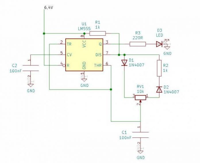
555 Timer PWM DC Motor Speed Controller Circuit Diagram
The output is taken from the usual pin#3 of the chip. In the above straightforward configuration the IC 555 is all set for generating the required PWM pulses, it just requires a square wave pulse or a clock input at its pin#2, which determines the output frequency, and a variable voltage input at pin#5 whose amplitude or the voltage level decides the pulse width dimensions at the output.

Working of the PWM Based DC Motor Speed Controller. The 555 Timer is configured in its astable mode, which means it will oscillate continuously between its high and low states, producing a square wave output.The frequency and duty cycle of this square wave (PWM signal) are determined by the resistors (R1, R3) and capacitors (C1, C2) connected to the 555 Timer.

Light Dimmer & Motor ... - YouTube Circuit Diagram
555 Timer Astable Mode Circuit Diagram. The following image shows a simplified circuit of 555 Timer IC in Astable Mode. Operation. I made a dedicated tutorial on "Astable Multivibrator using 555 Timer". For detailed explanation, check it out. To understand the working of the 555 Timer in Astable Mode, take a look at the internal circuit of
